

Power over Fiber in Solid-State Transformers: Floating Gate Drives and Monitoring
In a solid-state transformer, optical power is a candidate for highly isolated auxiliary supplies with low coupling. A solid-state transformer (SST) uses power-electronic conversion to manage energy transfer. Its floating gate drivers, acquisition circuits and monitoring electronics must operate reliably at different electrical potentials. Power over Fiber (PoF) delivers optical energy into those domains and converts it locally into electricity, reducing electrical coupling through the auxiliary power path.
This application design considers a power cell in a modular medium-voltage SST and draws on published research. The diagrams explain functional relationships; they do not represent a delivered system or field-validated performance.
The challenge: powering electronics at floating potential
A gate driver normally references the source or emitter of its power device. During switching, that local reference may move rapidly relative to the central controller. With fast SiC devices, the insulation structure, parasitic capacitance and routing of the auxiliary supply can affect common-mode interference and drive stability.
Even when PWM commands travel over fiber, a conventional isolated DC/DC supply can provide a common-mode current path through its isolation capacitance. The relationship iCM ≈ Ccoupling × dv/dt helps explain the issue. Signal isolation and supply isolation therefore need to be considered together.
Published research has demonstrated optically powered gate drives for high-voltage SiC MOSFETs, and SST research has identified optical gate-drive power with comprehensive protection as a development direction. This supports power-cell investigation, but does not establish complete-system maturity for every SST topology, power rating or operating condition.
Where it fits: gate drives first, monitoring where appropriate
Floating gate-drive supplies are the first application to assess. A low-voltage-side laser delivers light through dielectric fiber. A photovoltaic converter in the power cell produces DC power, which is regulated into the required gate-bias rails. Whether negative turn-off bias is needed, and the allowable voltage range, depend on the power device and drive strategy.
High-potential sensing and diagnostics are possible extensions. Module temperature sensing, local voltage acquisition and low-power diagnostic logic may be supplied optically where the power budget permits. Independent potential domains require separate isolation; sharing a supply must not introduce an electrical connection across them.
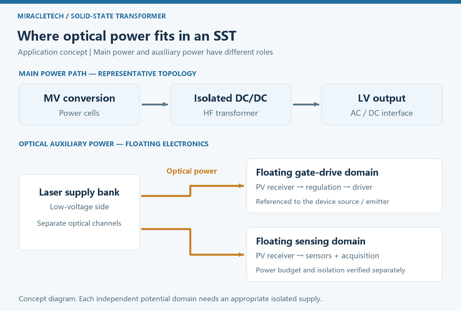
PoF serves these auxiliary electronics. The SST's main energy transfer still uses power semiconductors, magnetic components and its main circuit. Optical power does not replace the main transformer or supply the SST's kilowatt- or megawatt-scale load.
A power-cell design: separate power, commands and feedback
This case uses centrally managed lasers on the low-voltage side and independent receivers at floating potential. The photovoltaic converter, regulator, energy-buffer capacitors and driver reside within the same potential domain, with a short local gate loop. PWM commands and fault feedback use separate optical signal paths so that power delivery and communication timing can be verified independently.
In a half bridge, the upper and lower gate drivers may have different reference potentials. Centralized laser management does not remove the need to define each receiver's supply domain. If optical splitters are used, account for the splitting ratio, insertion loss, connectors and temperature differences between branches. Dividing source power by the number of channels is not a sufficient power-budget calculation.
Fiber reduces electrical coupling along specific power and communication paths. Parasitic paths remain between the driver board, heatsink, sensors and enclosure, and the local gate circuit can still oscillate. Appropriate layout, decoupling and system-level electromagnetic design remain necessary.
The power budget: distinguish average energy from current pulses
Estimate gate charging, driver quiescent consumption, protection, sensing and communication loads before selecting launched optical power. For a conventional gate drive without energy recovery, a first approximation for one device is:
Pgate ≈ Qg × ΔVgate × fs.
Use gate charge Qg appropriate to the operating conditions, the gate-voltage swing ΔVgate and switching frequency fs. Sum the contributions of multiple devices and channels, then include quiescent loads and design margin. Photovoltaic and regulation losses must be accounted for separately; received optical power is not usable electrical output.
Large, brief gate-current pulses are supplied mainly by local decoupling capacitors and the driver's output stage. The optical link replenishes average energy. Laser average power therefore does not directly specify peak gate-current capability. The buffer and regulator must also cover startup and the energy needed for fault shutdown.
Startup and faults: establish power before enabling switching
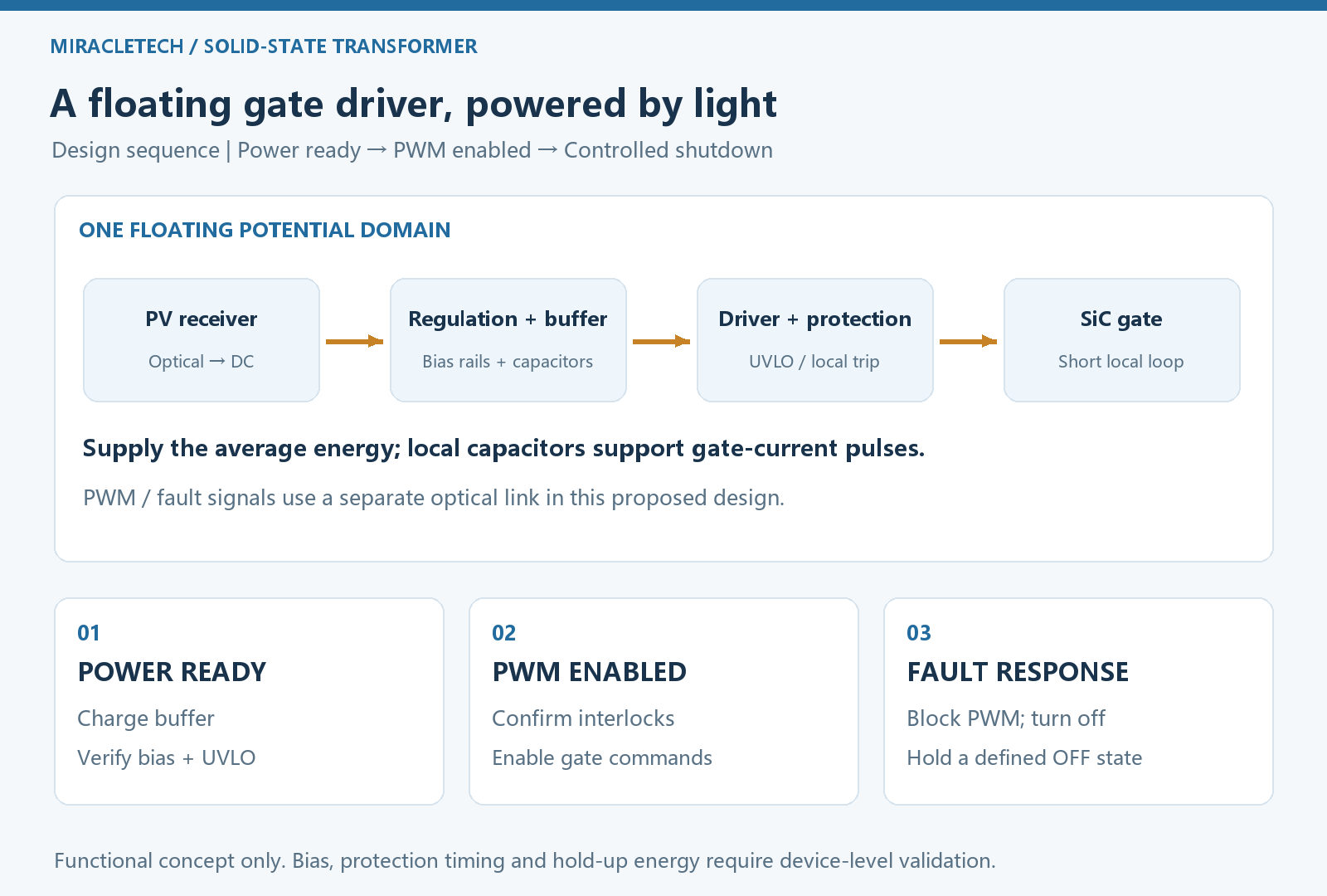
- Establish the supply: energize the optical link and charge the local buffer. Keep the power device off until bias voltages, undervoltage lockout and interlock conditions are satisfied.
- Enable drive commands: allow PWM only after the receiver reports readiness. Monitor bias, temperature and link status during operation to prevent switching with inadequate supply.
- Respond locally to faults: overcurrent, loss of light or abnormal bias should block drive commands and initiate the appropriate turn-off action. Fast protection must not wait for a round trip to the central controller.
- Maintain a defined off state: provide sufficient shutdown energy and a reliable gate-discharge path. Verify behavior after stored energy is depleted; switching off the laser does not, by itself, guarantee safe turn-off of the power device.
Protection thresholds, soft turn-off, Miller clamping and fault reporting must be selected for the actual device. PoF addresses the supply path; it does not replace the gate driver's protection functions.
Validation: progress from one channel to the SST power cell
Start by validating optical-channel power, temperature rise and startup. Then integrate the driver and power device for double-pulse and continuous-operation testing before expanding to a multi-channel power cell. The assessment should cover:
- Supply limits: regulation margin, startup time, peak loads and aging allowance at the worst expected optical loss and temperature.
- Switching behavior: gate waveforms, false triggering, propagation delay, channel skew and dead-time control at the actual dv/dt.
- Fault behavior: shutdown and recovery during fiber breaks, connector contamination, laser failure and undervoltage.
- Complete-system insulation: evaluate insulation, partial discharge, creepage paths and electromagnetic compatibility for the intended voltage class, construction and environment. Fiber material alone cannot establish system capability.
PoF merits consideration where isolation and common-mode interference are significant constraints. Its tradeoffs include conversion loss, receiver cooling, laser and connector cost, and multi-channel routing and maintenance. Where a conventional low-capacitance isolated supply already meets requirements, compare efficiency, cost and reliability before changing architectures.
A practical SST development path is to validate one demanding but power-manageable gate-drive channel first, then extend to monitoring circuits and further cells as the results justify. This ties the value of optical power to measurable supply performance, interference behavior and fault response.